555 Musical Circuit
Objective
Make a circuit with six pushbuttons that play musical notes.Schematic

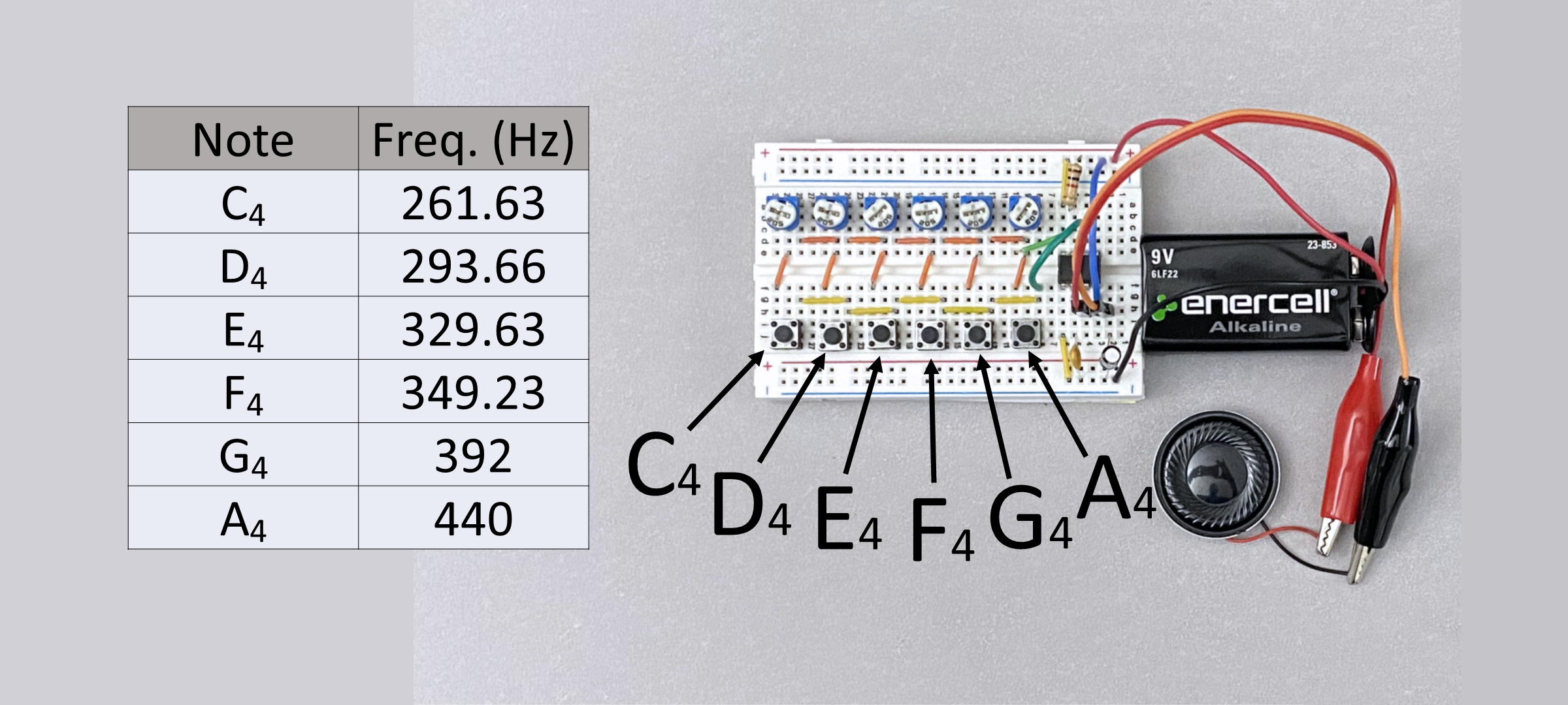
Final Result

Materials
Visuals & Additional Information
555 Timer Diagram
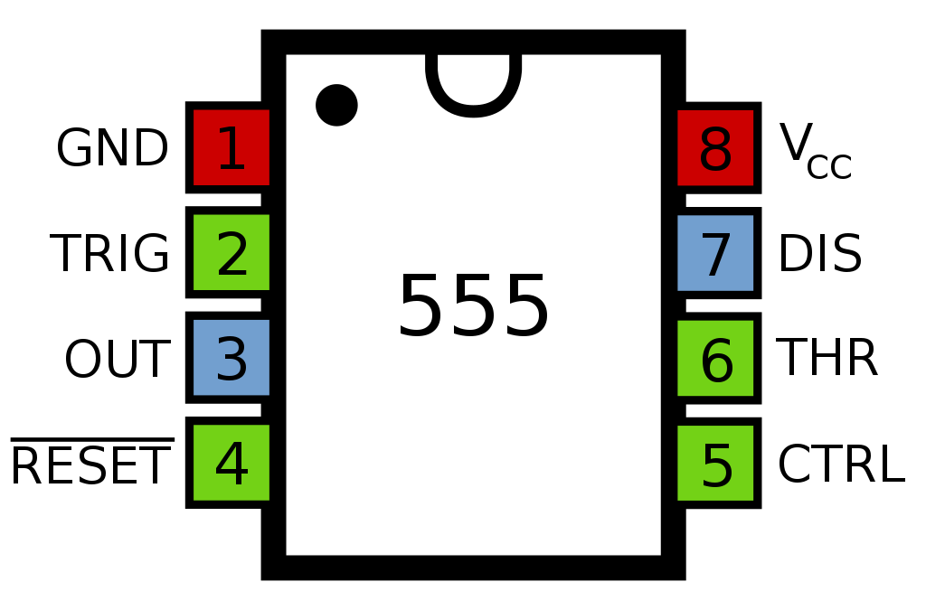
555 Timer IC Pinout

555 Timer IC Datasheet
Assembly Instructions
Step 1
Insert the 555 Timer IC into the breadboard.
Step 2
Connect pin 1 to the ground rail.
Step 3
Insert the 100 nf ceramic capacitor between pin 2 and the ground rail.
Step 4
Connect pin 2 and pin 6.
Step 5
Connect pin 8 to the positive rail.
Step 6
Insert the 1 kΩ resistor between pin 7 and the positive rail.
Step 7
Connect pin 4 to the positive rail.
Step 8
Insert the six pushbuttons into the last column of the breadboard. On my breadboard, the last column is column j.
Step 9
Insert jumpers to connect pin 2 of each pushbutton.
Step 10
Insert the jumpers that will connect pin 1 of each pushbutton to the middle pin of each trimmer potentiometer.
Step 11
Use jumpers to connect the middle pin and pin 3 of each trim pot.
Step 12
Insert the 20 kΩ trim pot.
Step 13
Use a jumper to connect pin 7 to pin 1 of the 20 kΩ trim pot.
Step 14
Use a jumper to connect pin 6 to pin 2 of pushbutton 1.
Step 15
Insert the 5 kΩ trim pots.
Step 16
Insert the positive lead of the 22 uF electrolytic capacitor into column j.
Step 17
Connect the negative lead of the 22 uF electrolytic capacitor to the ground rail.
Step 18
Connect the gator clips to the 8 Ω speaker.
Step 19
Connect one wire of the gator to male jumper to pin 3 of the 555 Timer.
Step 20
Connect the other wire of the gator to male jumper to the positive lead of the 22 uF capacitor.
Step 21
Connect the negative lead of the 9V battery to the ground rail.
Step 22
Connect the positive lead of the 9V battery to the positive rail.
Step 23
Adjust the 20 kΩ trim pot until pushbutton 1 generates a frequency of approximately 440 Hz.
Step 24
Adjust the 5 kΩ trim pot until pushbutton 2 generates a frequency of approximately 392 Hz.
Step 25
Adjust the 5 kΩ trim pot until pushbutton 3 generates a frequency of approximately 349.23 Hz.
Step 26
Adjust the 5 kΩ trim pot until pushbutton 4 generates a frequency of approximately 329.63 Hz.
Step 27
Adjust the 5 kΩ trim pot until pushbutton 5 generates a frequency of approximately 293.66 Hz.
Step 28
Adjust the 5 kΩ trim pot until pushbutton 6 generates a frequency of approximately 261.63 Hz.
Created By
Revision History
| Date | Description | Version |
|---|---|---|
| JAN 05 2024 | Started | Draft |